+86 123 456 7890



+86 123 456 7890
Nov.12,2026
Crosshead clearance is an important factor affecting the performance and reliability of a drilling mud pump's power end.
Incorrect running clearance, worn guide plates, poor alignment, and lubrication problems can contribute to increased friction, abnormal mechanical noise, and accelerated wear.
For drilling contractors, mud pump maintenance engineers, and spare parts buyers, understanding crosshead clearance helps identify potential problems and evaluate replacement requirements.
This guide explains how crosshead clearance is measured, why guide plate alignment matters, and how to inspect related power end components, using F-1300/F-1600 mud pumps as a technical reference.
It also includes real manufacturing and inspection footage from FH Petroleum Machinery.
 Mud pump crosshead body with optional copper-alloy sliding shoes
The crosshead is a major reciprocating component located inside the mud pump power end.
It transfers mechanical motion from the connecting rod mechanism to the crosshead extension rod, helping convert crankshaft rotation into controlled linear movement.
During operation, the crosshead travels along guide surfaces inside the pump frame.
Upper and lower crosshead guide plates provide the corresponding sliding surfaces and help maintain the required alignment.
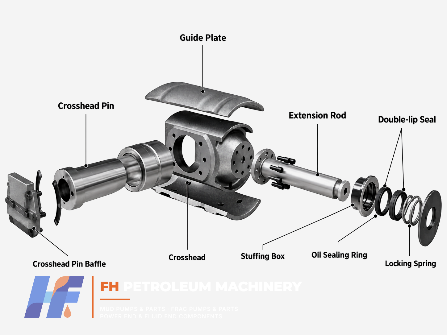 Technical exploded illustration of mud pump crosshead components
Crosshead running clearance refers to the designed gap between the crosshead sliding surface and its corresponding guide.
The appropriate clearance depends on the pump model, component design, operating configuration, and manufacturer requirements.
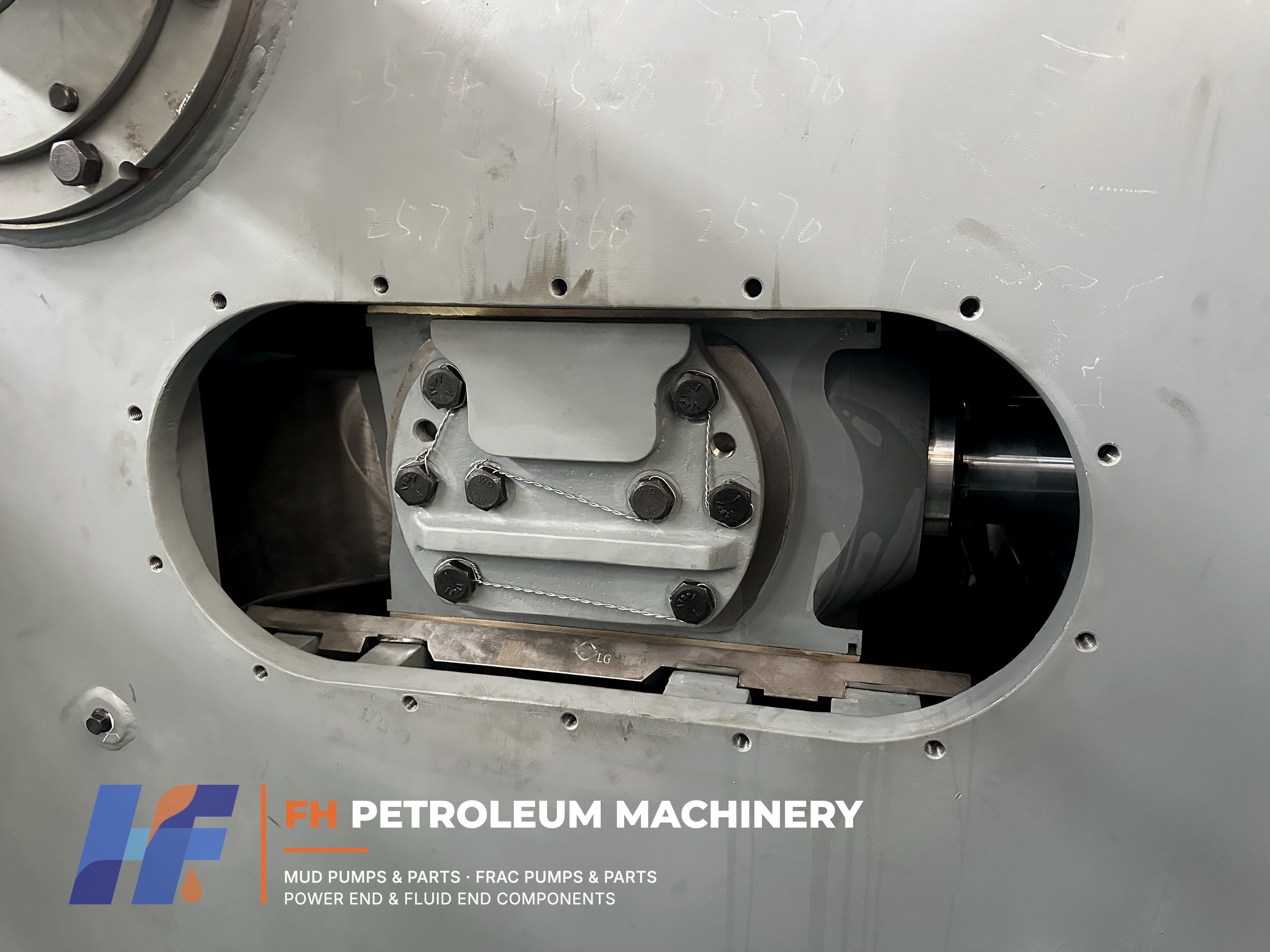
Mud Pump Power End | Crosshead & Guide Plate Assembly Inspection
Inside a Mud Pump Power End
A real view of the crosshead and guide plate arrangement inside a drilling mud pump power end.
If clearance is too small, sliding surfaces may experience excessive friction, inadequate lubrication, heat generation, or mechanical damage.
If clearance is excessive, the crosshead may experience abnormal movement or contact conditions that contribute to wear and mechanical noise.
However, clearance is only one aspect of power end condition. Lubrication, surface geometry, guide alignment, contamination, and the condition of associated components must also be evaluated.
Crosshead clearance values must be obtained from the operation and maintenance manual applicable to the actual pump.
The F-1300/F-1600 drilling pump operation manual issued by Baoji Oilfield Machinery Co., Ltd. provides the following reference information for the described configuration:
| Inspection item | Reference |
|---|---|
| Upper crosshead running clearance | 0.45–0.56 mm |
| Equivalent value | 0.018–0.022 in |
| Measuring instrument | Long feeler gauge |
| Measuring position | Crosshead upper surface and upper guide |
| Inspection approach | Check across the specified upper surface |
The manual also contains separate guidance on crosshead alignment and guide adjustment.
For its forward-rotation arrangement, the lower guide carries the primary operating load.
The guide adjustment procedure specifies that upper clearance must not be reduced below 0.50 mm.
The manual also identifies a different clearance range of 0.25–0.40 mm for the reverse-rotation configuration it describes.
These values are model- and procedure-specific.
They must not be applied automatically to other F-Series pumps, National P-Series pumps, or different crosshead designs.
Technical reference:
Baoji Oilfield Machinery Co., Ltd., F-1300/F-1600 Drilling Pump Operation Manual, Sections 3.4.9–3.4.11.
Reference document:
https://ar.rdpmc.com/1600-drilling-pump-operation-manual.pdf
Crosshead clearance inspection should be performed by qualified maintenance personnel using the manufacturer's prescribed procedure.
Stop the equipment, isolate energy sources, prevent unexpected movement, and follow the applicable site safety procedures.
Access the crosshead inspection area according to the maintenance manual.
Locate the crosshead body and the relevant upper guide surface.
Identify the specified measuring position for the particular pump model.
Inspect accessible sliding surfaces for visible damage, contamination, scoring, and other abnormal conditions.
Make sure the measuring area is sufficiently clean for reliable inspection.
For the referenced F-1300/F-1600 configuration, the manufacturer specifies checking the gap between the upper crosshead surface and upper guide using a suitable long feeler gauge.
Measurements should cover the specified surface rather than relying on a single point.
Record the readings and compare them with the correct manufacturer specifications.
If the results are outside the required range, inspect the guide surfaces, alignment, lubrication system, and related components before determining the corrective action.
Guide adjustment and shimming must follow the applicable pump manual.
Important: Factory dimensional inspection and guide plate surface inspection are different from measuring actual crosshead running clearance in an assembled pump.
Several operating and mechanical conditions can contribute to crosshead wear.
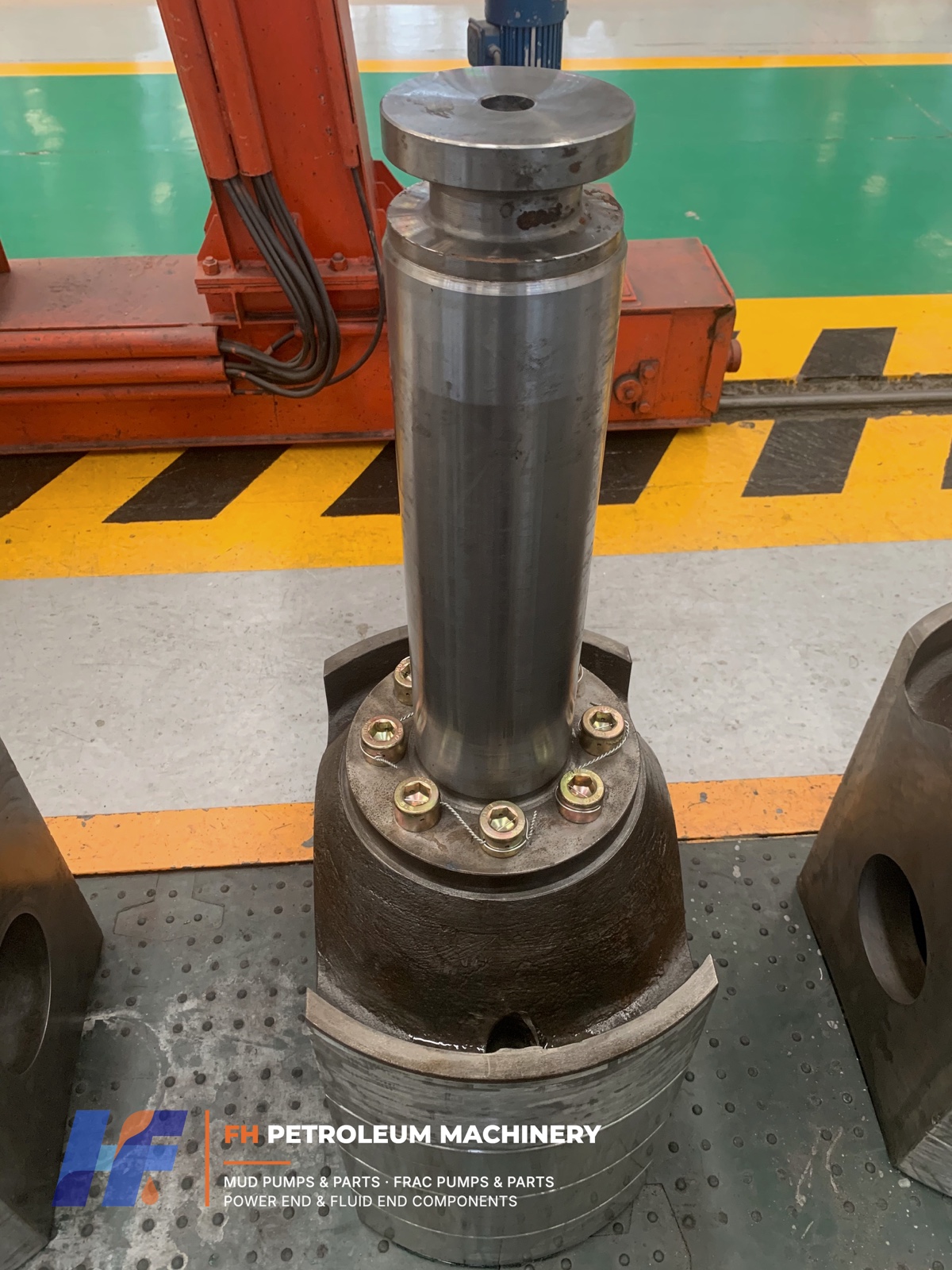 Used mud pump crosshead body removed from service for inspection
Visible scoring may be associated with lubrication problems, contamination, damaged mating surfaces, or abnormal friction.
The severity of surface damage must be assessed through inspection.
Uneven contact patterns may indicate misalignment, localized loading, geometry deviations, or other mechanical issues.
Inspection should include the mating guide surfaces and relevant dimensional measurements.
Knocking or impact sounds may indicate excessive clearance or other mechanical problems within the power end.
Noise alone does not establish that the crosshead has failed.
Insufficient lubrication, contaminated oil, or blocked oil passages can accelerate deterioration of sliding interfaces.
The lubrication system should be included in a complete maintenance assessment.
Previously operated crosshead bodies may show visible sliding contact marks and surface changes.
These observations can help identify areas requiring closer inspection, but photographs alone cannot establish allowable wear limits or determine whether a component must be replaced.
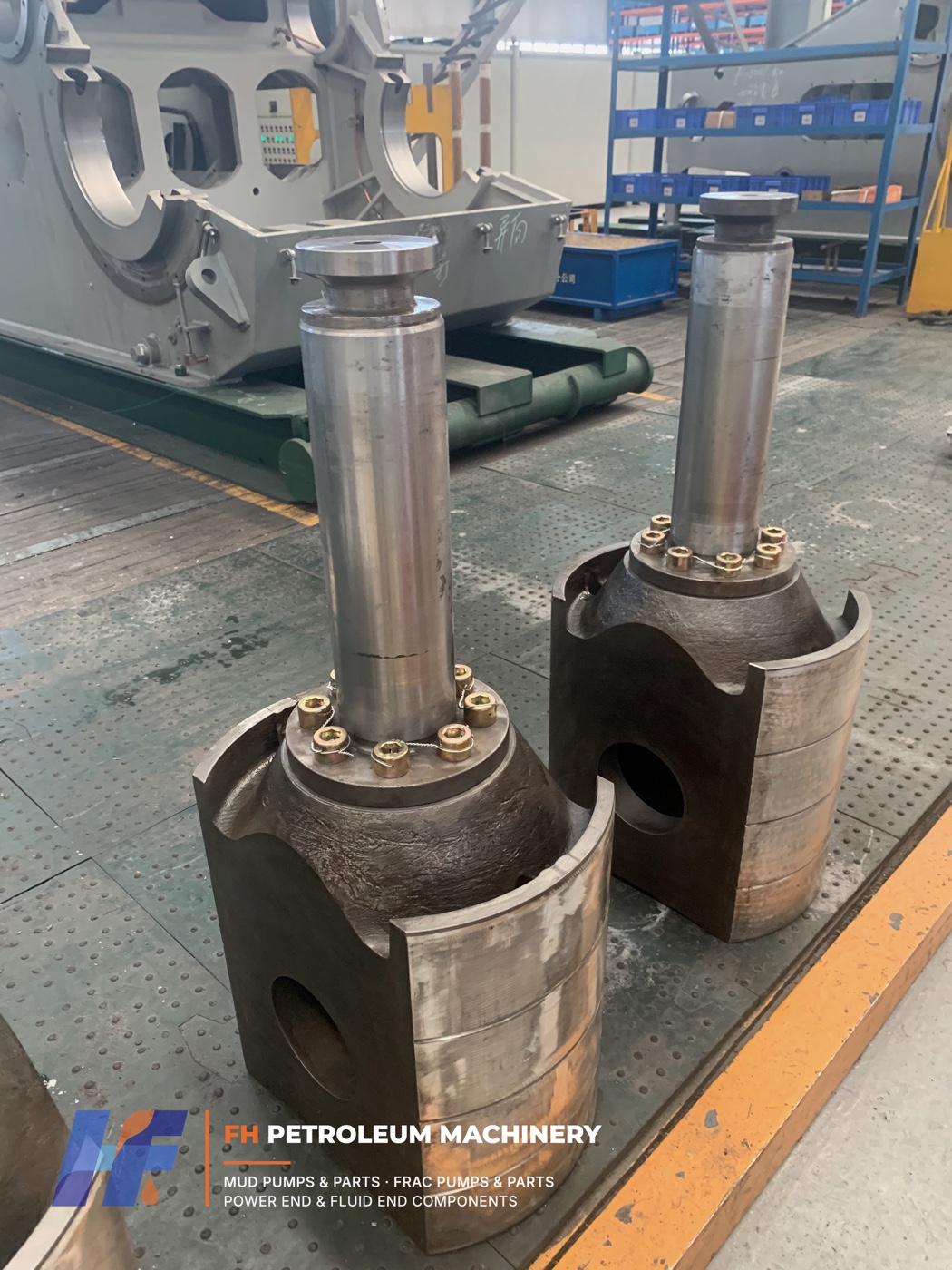 Previously operated mud pump crosshead components with visible sliding surfaces
Crosshead guide plates provide sliding surfaces and help control the linear movement of the crosshead.
Their shape, dimensions, installation arrangement, and adjustment requirements depend on the pump design.
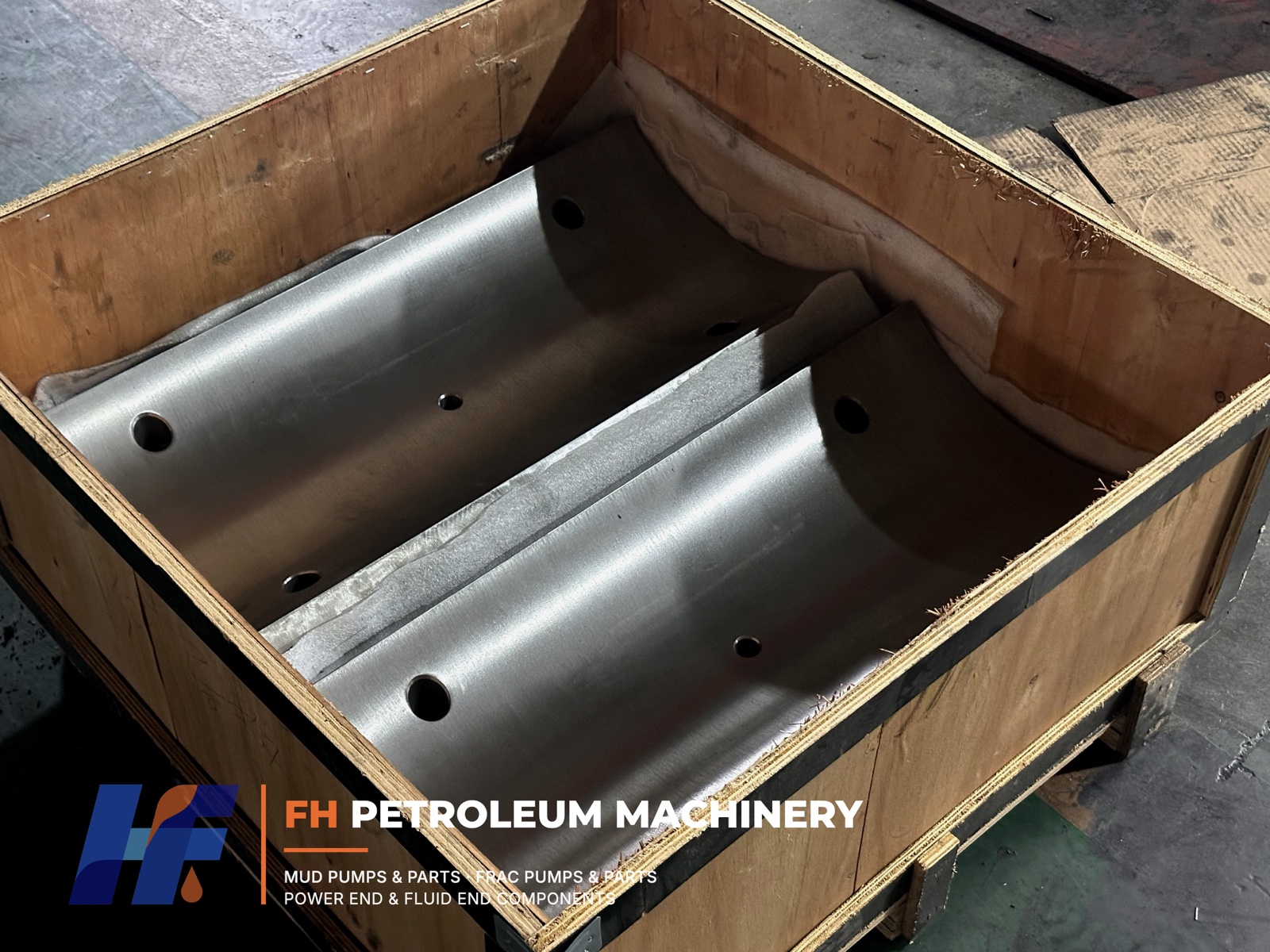 Precision-machined mud pump crosshead guide plates
In the referenced F-1300/F-1600 configuration, upper and lower crosshead guides are not interchangeable.
The lower guide helps position the crosshead relative to the frame centerline, while the upper guide provides the required operating clearance.
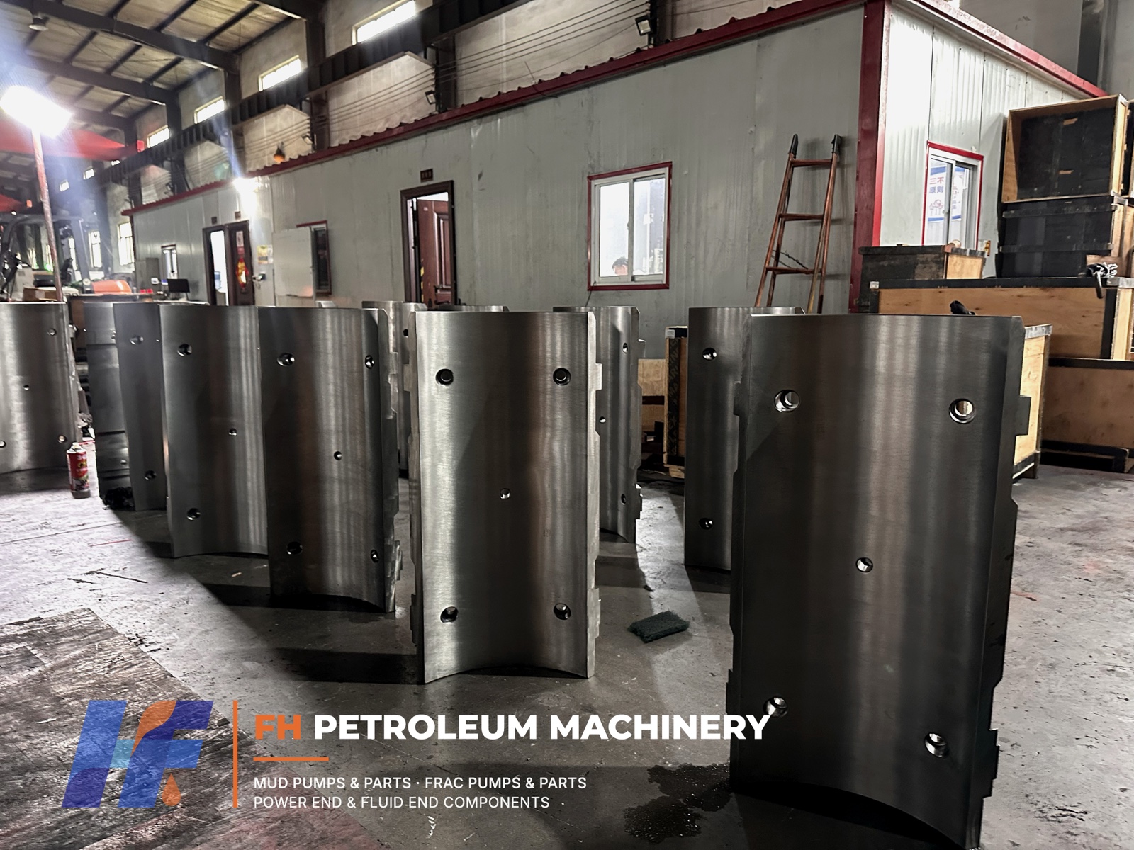 Crosshead guide plates manufactured for mud pump power ends
During maintenance, engineers should check:
FH Petroleum manufactures upper and lower crosshead guide plates according to customer drawings, approved samples, or verified technical requirements.
Because guide plates are position- and model-specific, buyers should not assume that parts from different pump models are interchangeable.
Mud Pump Crosshead Guide Plate – Surface & Design Details
Crosshead Guide Plate Details
A close-up view of crosshead guide plate geometry and machined surfaces.
Manufacturing quality is an important factor in the performance of crosshead guide components.
Relevant manufacturing characteristics include dimensional accuracy, surface geometry, surface finish, and consistency with the approved engineering drawing.
Precision machining helps achieve the required component geometry.
Surface and dimensional inspections help verify that the manufactured parts conform to the specified requirements.
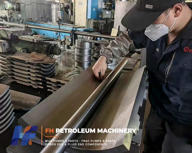 Factory inspection of mud pump crosshead guide plate surface
FH Petroleum's workshop footage shows actual guide plate surface inspection and finished component details.
These factory inspections demonstrate manufacturing and quality control activities.
They are not presented as measurements of the running clearance inside an assembled mud pump.
FH Petroleum manufactures standard mud pump crosshead bodies and optional configurations incorporating copper-alloy sliding shoes according to customer requirements.
A standard crosshead body does not incorporate the additional copper-alloy sliding shoe configuration.
It is manufactured according to the specified pump design, technical drawing, and dimensional requirements.
For certain customer-specific designs, copper-alloy sliding shoes can be incorporated into the crosshead body.
This optional configuration is intended to improve sliding surface wear resistance and may contribute to longer service life under appropriate lubrication and operating conditions.
Once installed, the copper-alloy sliding shoes are treated as functional parts of the crosshead body.
They are not intended to be individually replaced as routine field maintenance items.
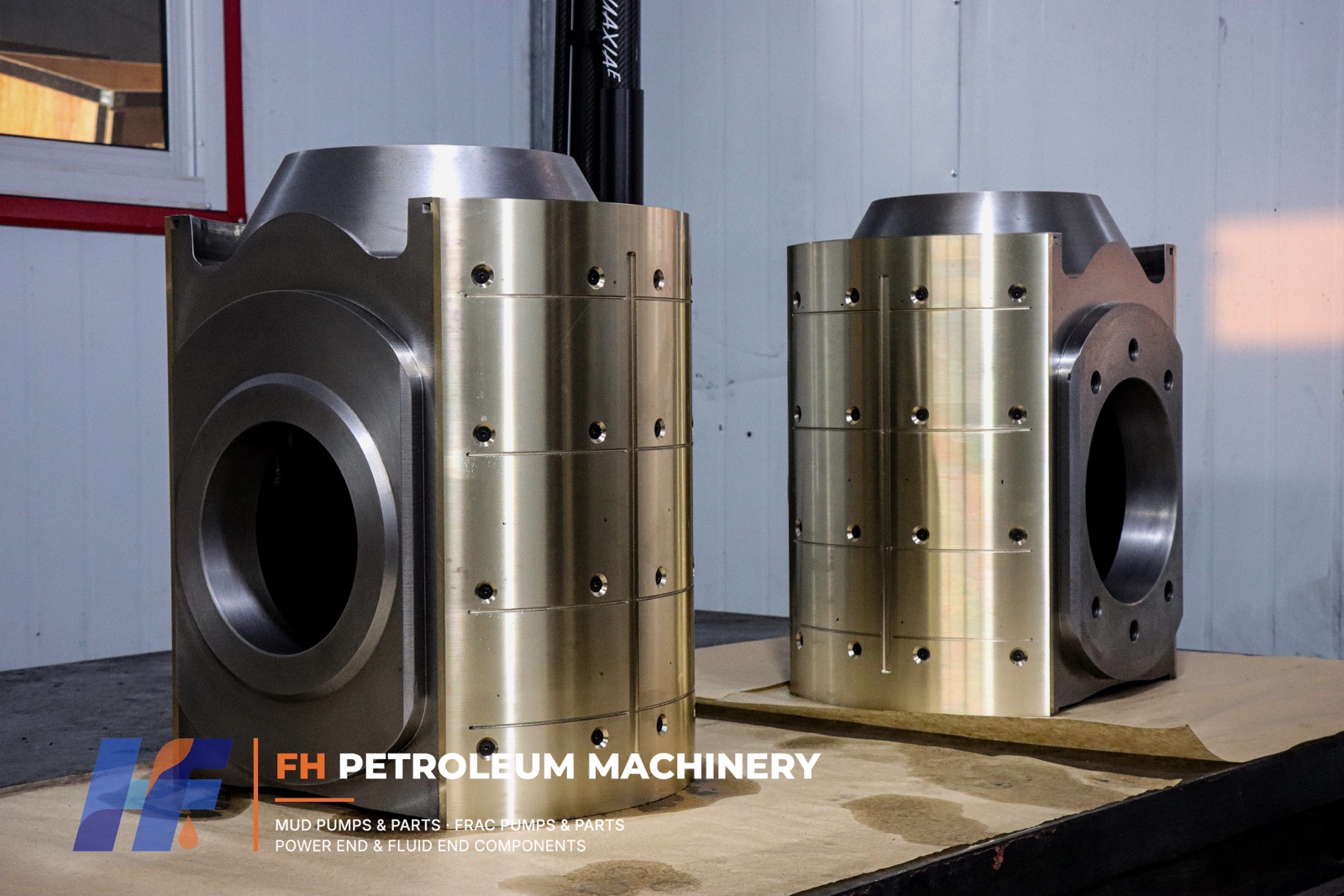 Crosshead body with optional segmented copper-alloy sliding shoes
When the relevant crosshead body requires replacement, it is replaced as a unit rather than removing and replacing the copper-alloy shoes separately.
A crosshead body is not necessarily the same as a complete crosshead assembly.
The broader assembly may include the crosshead body, connecting rod and associated mechanical components, depending on the equipment design and assembly drawing.
These terms should be distinguished when ordering replacement parts.
Crosshead bodies require controlled manufacturing processes to achieve the specified geometry and dimensional accuracy.
Machining accuracy is especially important where the crosshead interfaces with guide surfaces, connecting components, and related power end parts.
FH Petroleum manufactures crosshead bodies using machining procedures based on approved drawings and technical requirements.
Coordinate measuring machine (CMM) inspection may be used to verify relevant dimensional and geometric characteristics.
The following workshop videos show actual crosshead machining and CMM inspection processes.
Mud Pump Crosshead CNC Machining | Precision Manufacturing at FH Petroleum
Crosshead CNC Machining
Real workshop footage showing the machining of a mud pump crosshead body at FH Petroleum.
Mud Pump Crosshead CMM Inspection | Precision Dimensional Quality Control
Crosshead Dimensional Inspection
Coordinate measuring machine inspection of a machined mud pump crosshead component.
These manufacturing activities support component quality control but do not replace the running clearance inspection required after installation in the pump.
Replacement decisions should be based on component condition and the applicable maintenance specifications.
Factors requiring additional evaluation may include:
There is no universal replacement interval that applies to every mud pump.
Service requirements depend on design, load, operating conditions, maintenance quality, and component condition.
For crosshead bodies incorporating copper-alloy sliding shoes, replacement is performed at the crosshead body level rather than by separately replacing individual copper-alloy shoes.
FH Petroleum Machinery manufactures power end components for drilling mud pumps, including:
We work with mud pump OEMs, equipment maintenance companies, distributors, and international industrial buyers.
Manufacturing can be arranged according to customer drawings, confirmed dimensions, approved samples, and specific technical requirements.
For crosshead bodies, guide plates, or other mud pump replacement components, please provide:
FH Petroleum Machinery
Website: https://www.fhpetroleum.com/
Email: sales@fhpetroleum.com
The referenced BOMCO F-1300/F-1600 manual specifies an upper running clearance of 0.45–0.56 mm for its described configuration. The correct requirement must be verified against the actual pump manual and operating configuration.
The relevant manufacturer procedure may require a long feeler gauge to check the specified gap between the crosshead and guide surface. The exact measuring position depends on the pump design.
Not for the F-1300/F-1600 configuration covered by the referenced BOMCO manual. The upper and lower guides perform different functions and have different dimensional requirements.
Potential causes include inadequate lubrication, contamination, misalignment, abnormal loading, damaged sliding surfaces, and incorrect running clearance.
No. Standard crosshead bodies do not incorporate this optional configuration. Copper-alloy sliding shoes are available for applicable designs based on customer requirements.
For FH Petroleum's described optional configuration, the installed sliding shoes are treated as part of the crosshead body rather than individually replaceable field maintenance items.
FH Petroleum can review customer drawings, approved samples, and technical specifications for replacement or customized production. Manufacturing feasibility and dimensional requirements are subject to engineering review.
Technical Disclaimer
This article provides general maintenance information together with selected reference data from the specified F-1300/F-1600 pump manual. It does not replace the original equipment manufacturer's maintenance instructions. Inspection, alignment, and adjustment work must be performed by qualified personnel following the correct specifications for the actual pump.
Need Mud Pump Parts Or Equipment?
Send us your drawing, model number or requirements.Our engineers will reply within 24 hours.